Gallery Homemade DC Electronic Load Hackaday.io
Click "Like" to get coupon: https://jlcpcb.com/Workshop-PCB-Project-Competiton$2/5pcs 2Layer & $5/5pcs 4Layer PCBs: https://jlcpcb.com🔥This is a second ver.
A DIY Electronic load for DCDC converter characterization
With that out of the way, I would like to present my conceptual approach to the CC, CV and CR mode electronic load in an (IMO) elegant mostly analog circuit using 2 switches, 2 potentiometers and a bunch of resistors/caps. Feedback is appreciated.
DIY KIT Electronic LOAD schematic and Komitart LAY6.
December 29, 2023 Build Your Own Active Load 28 Comments by: Lewin Day February 11, 2020 When it comes to testing power supplies, it's useful to have a dummy load to put the gear through its.
DIY ELECTRONIC LOAD 600 Watt schematic with Komitart LAY6.
Building A DC Constant Current/Power Electric Load. 47 Comments. by: Mathieu Stephan. October 28, 2013. electric load. For those who don't know, an electric load (or dummy load) is a device used.

Carga electrónica de 180watt 200V/20A DIY 300watt (Electronic load 180wat) YouTube
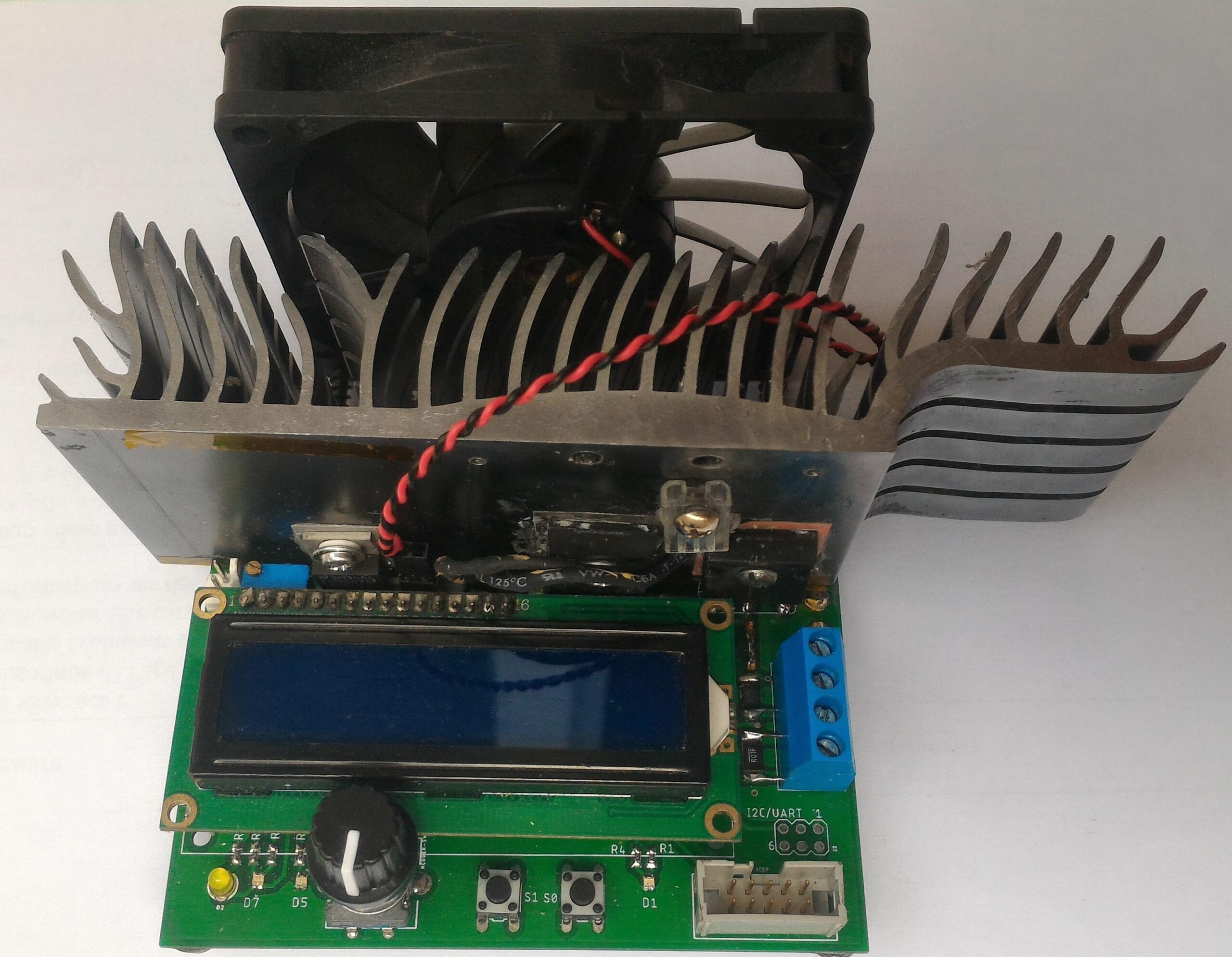
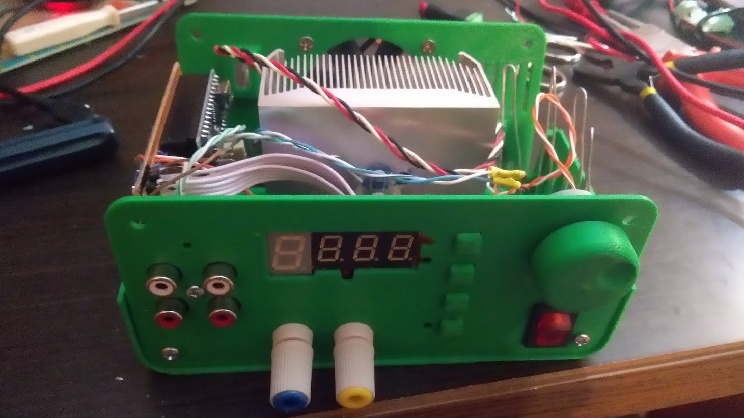
Main specs: - 24V max, <6A max, (withstand continuous 5A@12V; used heatsink limited) - generic Arduino Nano controlled - use of external ADC & DAC modules for improved resolution/precision and simplification - temperature limit control and active (pwm) fan cooling - simple UI - small 0.96" 128x64 OLED screen, one button and a rotary encoder

DIY electronic load Sponsor PCBWay
EEVBLOG electronic load This project was created on 02/26/2019 and last updated 3 years ago. Description I needed an electronic load for testing DC-DC boost converters but didn't want to buy one (they're expensive!). I saw Dave Jones of the EEVBlog build a pretty handy looking electronic load very simply using a transistor current source.

DIY USB electronic load YouTube
In this tutorial, we will learn how to build our very own Adjustable Electronic Load using Arduino, which can take a maximum input voltage of 24V and drain current as high as 5A. For this project, we have used PCB boards which are manufactured by AllPCB, a china based professional PCB manufacturing and assembling service provider.

DIY ELECTRONIC LOAD 600 Watt schematic with Komitart LAY6.
Figure 1: Schematic For 3A Load Box The opamp, an LT1635, also contains a buffered 200mV reference (U1a) which is amplified to obtain 3V. I trimmed the output current to 3A by adding 2MΩ across R6. If you want to make a fully adjustable load box, add a 1MΩ log taper pot or 10-turn 100kΩ pot between U1a and U1b.

Homemade Digital Electronic Load Multiple Modes YouTube
An encoder is used for current adjustment. By default, the current can be adjusted at a resolution of approximately 1mA/step. By pressing the encoder button, this resolution can be changed to 10mA/step and 100mA/step respectively. This makes it easier to to coarse adjustments. Constant power mode is achieved by calculating the desired set.

DIY electronic load Sponsor PCBWay
Step 1: Watch the Video! The video gives you all the information you need to make your own adjustable constant load. During the next steps though, I will present you some additional information. Ask Question Step 2: Order the Components! Here you can find a parts list with example seller (affiliate links): Aliexpress:

DIY DC Electronic Programmable Load 5 Steps Instructables
The operating principle is very simple; custom PCBs act in parallel to provide any load needed, by switching in the on-board load resistor. Each load board handles all the details of.
DIY Electronic Load PCB Kit for Testing Power Supplies FiveFish Audio
Here are the lab's current electronic loads: Figure 2 Manually-adjustable electr (on)ic loads I could mount these in the supply chassis along with a fan. But it might be nice to have a true electronic load - something with a bit more functionality. Something that doesn't require a screwdriver to adjust. Something like:
DIY Electronic LOAD 300 Watt schematic with Komitart LAY6.
An electronic load, also known as a constant current dummy load, is a device design so a power supply can draw a certain amount of current without dissipating too much of heat. Basically, when you dial in a current level, the electronic load circuitry will draw only that amount of current, regardless of the voltage.

DIY Adjustable Electronic DC Load 5 Steps (with Pictures) Instructables
By biasing the motor with a small DC voltage applied to one lead and reading the resulting voltage from the other, the knob's speed and direction can be detected, doing a serviceable job as rotary.
Spot This DIY Electronic Load’s Gracefully Hidden Hacks Hackaday
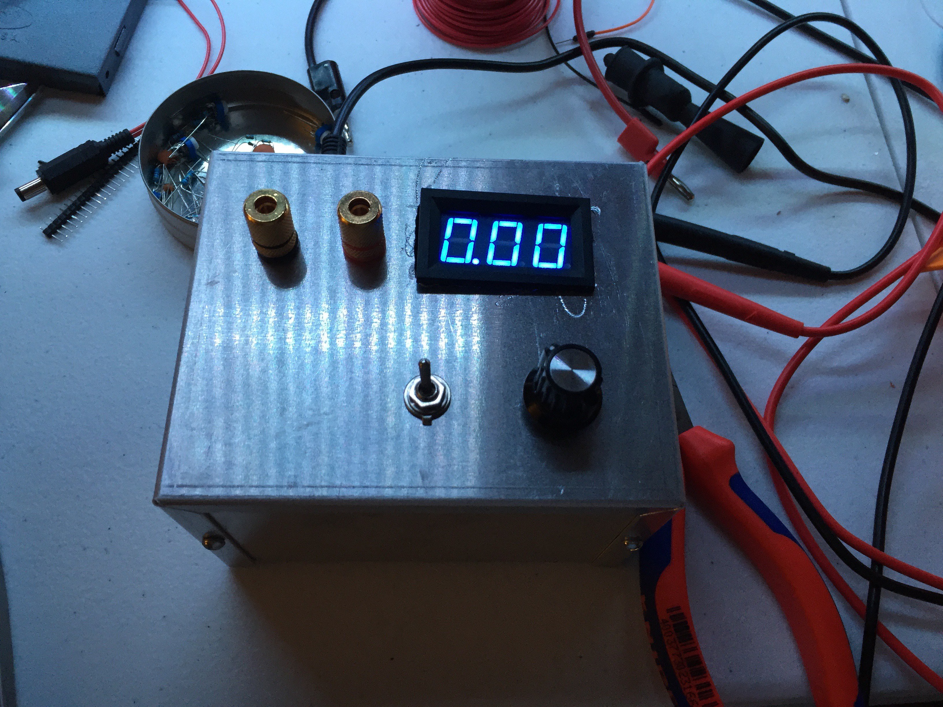
DIY Adjustable Electronic DC Load By voltlog in Circuits Electronics 22,947 104 2 Featured Download By voltlog Visit my website! Follow More by the author: About: Electronics enthusiast, vlogger on youtube. More About voltlog » In this project I am building an analog adjustable dc load with parts easily obtainable from ebay and banggood.
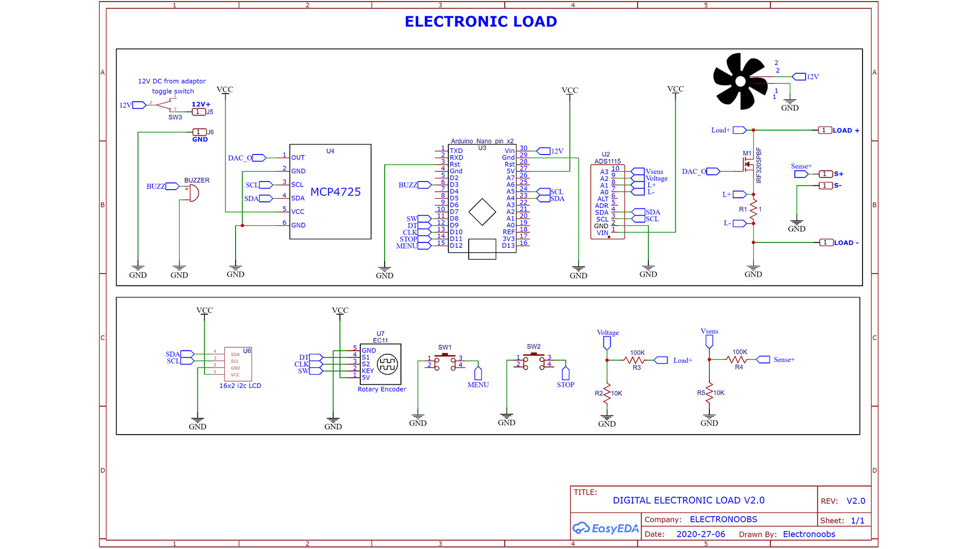
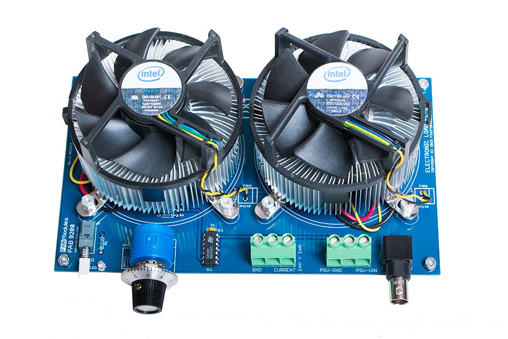
Arduino homemade electronic load schematic
Electronic Load This repository hosts my work in developping a custom electronic load from scratch. For more information on what an electronic load does and what it can be used for, see this.
